
Page 59 - Modern Control of DC-Based Power Systems
P. 59
24 Modern Control of DC-Based Power Systems
Switching converter
Power Load
input V
V
V g R network Sensing
Feedback
Transistor
gate driver Compensator connection
Current I L
modulator
I co
G c (s) –
+
Voltage
V ref
reference
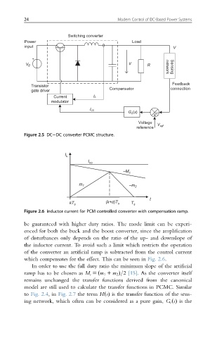
Figure 2.5 DC DC converter PCMC structure.
I L
I co
–M c
m 1 –m 2
t
(k+d)T
kT s s T s
Figure 2.6 Inductor current for PCM controlled converter with compensation ramp.
be guaranteed with higher duty ratios. The mode limit can be experi-
enced for both the buck and the boost converter, since the amplification
of disturbances only depends on the ratio of the up- and downslope of
the inductor current. To avoid such a limit which restricts the operation
of the converter an artificial ramp is subtracted from the control current
which compensates for the effect. This can be seen in Fig. 2.6.
In order to use the full duty ratio the minimum slope of the artificial
ramp has to be chosen as M c 5 ðm 1 1 m 2 Þ=2 [15]. As the converter itself
remains unchanged the transfer functions derived from the canonical
model are still used to calculate the transfer functions in PCMC. Similar
to Fig. 2.4,in Fig. 2.7 the term HsðÞ is the transfer function of the sens-
ing network, which often can be considered as a pure gain, G c sðÞ is the