
Page 61 - Modern Control of DC-Based Power Systems
P. 61
26 Modern Control of DC-Based Power Systems
Table 2.2 Gains for PCMC Coefficients [11]
F v F g
Buck 1 2 2D D 2
2Lf sw 2Lf sw
Boost ð 12DÞ 2 2D 2 1
2Lf sw
2Lf sw
Buck Boost 2 12DÞ 2 D 2
ð
2Lf sw 2Lf sw
Middlebrook [12] criterion states that Z out , Z in for stable operation.
Therefore often the output impedance has to be reduced via feedback of
the output current to reduce the interactions with the load.
2.3 CASCADED SYSTEM (VMC)
Cascading two DC DC converters means that the downstream
converter, now referred to as converter 2 or Point of Load Converter
(POL), acts as the load of the upstream converter now labeled as con-
verter 1 or also called Line Regulating Converter (LRC). Using the
canonical model presented in Fig. 2.2, and under the small-signal assump-
tion, the system behavior is considered linear; thus, applying the two port
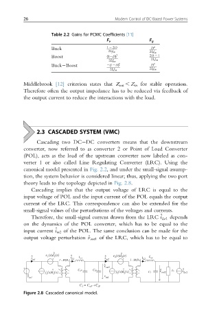
theory leads to the topology depicted in Fig. 2.8.
Cascading implies that the output voltage of LRC is equal to the
input voltage of POL and the input current of the POL equals the output
current of the LRC. This correspondence can also be extended for the
small-signal values of the perturbations of the voltages and currents.
Therefore, the small-signal current drawn from the LRC ^ i Lo1 depends
on the dynamics of the POL converter, which has to be equal to the
input current ^ i in2 of the POL. The same conclusion can be made for the
output voltage perturbation ^ out1 of the LRC, which has to be equal to
v
^ ^
e (s)d (s) ^ (s)d (s)
^ 1 1 L ^ e 2 2 L
i
i in1 1 : M(D 1) i L1 e1 i in2 1 : M(D 2) L2 e2
v ^ out1
^ C oF C iF ^ ^ Z 2 i ^
(s)d (s) j (s)d (s) v out2
j 1 2 2 C 2 Lo2
^ v 1
in1 v in1
C = C +C iF
oF
1
Figure 2.8 Cascaded canonical model.