
Page 66 - Modern Control of DC-Based Power Systems
P. 66
Small-Signal Analysis of Cascaded Systems 31
1 n 0 R
s ðÞ 5 52 (2.31)
e ss 5 lim s Z IN CL 2
s-0 s d 0 D
What has to be noted is that by using Eq. (2.30) instead of Eq. (2.28)
it is assumed that no dynamic interactions will take place between the
converters, which is a very optimistic assumption, particularly when con-
sidering that the POL converters are operating at a higher switching fre-
quency than the LRC.
In this chapter the limitations of an idealized behavior for a CPL char-
acteristic are addressed. The CPL characteristic is dependent on the con-
trol cycle of the converter [2].In Fig. 2.10, a buck converter supplying a
resistive load is depicted. For the upcoming analysis in the frequency
domain a linear behavior is assumed.
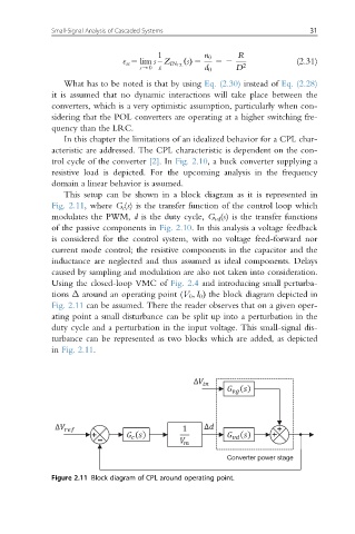
This setup can be shown in a block diagram as it is represented in
Fig. 2.11, where G c (s) is the transfer function of the control loop which
modulates the PWM, d is the duty cycle, G vd (s) is the transfer functions
of the passive components in Fig. 2.10. In this analysis a voltage feedback
is considered for the control system, with no voltage feed-forward nor
current mode control; the resistive components in the capacitor and the
inductance are neglected and thus assumed as ideal components. Delays
caused by sampling and modulation are also not taken into consideration.
Using the closed-loop VMC of Fig. 2.4 and introducing small perturba-
tions Δ around an operating point (V 0 ; I 0 Þ the block diagram depicted in
Fig. 2.11 can be assumed. There the reader observes that on a given oper-
ating point a small disturbance can be split up into a perturbation in the
duty cycle and a perturbation in the input voltage. This small-signal dis-
turbance can be represented as two blocks which are added, as depicted
in Fig. 2.11.
Converter power stage
Figure 2.11 Block diagram of CPL around operating point.