
Page 67 - Modern Control of DC-Based Power Systems
P. 67
32 Modern Control of DC-Based Power Systems
The close-looped transfer function of input voltage to output voltage
can be represented as:
ΔV out G vg ðsÞ
5 (2.32)
ΔV in 1
1 1 G c sðÞG vd sðÞ
V M
By assuming the structure depicted above the transfer function
between ΔV out and ΔV in is derived under the assumption that G vd (s) can
be characterized as a second-order system and that G c corresponds to the
transfer function of a PID controller. Without restricting the generality, a
constant gain of 1 for V M is considered. The values of the gains are set to
conduct a pole-zero cancellation K p 5 1 5 a; K I 5 1 5 b .
K D RC K D LC
̅
Kd
G vg ðsÞ 5 1 1
LCðs 1 s 1 Þ
2
RC LC
V in KV in
G vd s ðÞ 5 1 1 5 2
2
LCðs 1 s 1 Þ s 1 as 1 b
RC LC (2.33)
!
K D 2 K P K I
G c sðÞ 5 s 1 s 1
s K D K D
̅
sK d
ΔV out
5
2
ΔV in 5 ð s 1 K D KV in Þ s 1 as 1 bÞ
ð
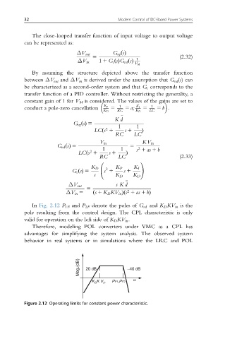
In Fig. 2.12 P 1F and P 2F denote the poles of G vd and K D KV in is the
pole resulting from the control design. The CPL characteristic is only
valid for operation on the left side of K D KV in .
Therefore, modeling POL converters under VMC as a CPL has
advantages for simplifying the system analysis. The observed system
behavior in real systems or in simulations where the LRC and POL
Mag.(dB) 20 dB –40 dB
K K V in PF1,PF2 ω
D
Figure 2.12 Operating limits for constant power characteristic.