
Page 62 - Modern Control of DC-Based Power Systems
P. 62
Small-Signal Analysis of Cascaded Systems 27
v
the input voltage perturbation ^ in2 of the POL. It is assumed that in cas-
cading two converters the LRC is only supplying one POL and therefore
the load impedance Z, which appears in Fig. 2.2, is eliminated. And
instead, the small-signal model of the converter in Fig. 2.2 is again used
and leads to the representation above.
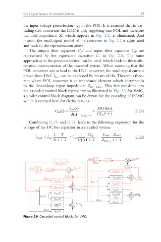
The output filter capacitor C oF and input filter capacitor C iF are
represented by the equivalent capacitor C 1 in Fig. 2.8. The same
approach as in the previous section can be used, which leads to the math-
ematical representation of the cascaded system. When assuming that the
POL converter acts as load to the LRC converter, the small-signal current
drawn from LRC ^ i Lo1 can be expressed by means of the Thevenins theo-
rem where POL converter is an impedance element which corresponds
to the closed-loop input impedances Z IN CL2 . This fact translates into
the cascaded control block representation illustrated in Fig. 2.9 for VMC,
a similar control block diagram can be drawn for the cascading of PCMC
which is omitted here for clarity reasons.
MD
^ v out ðsÞ
G vd ðsÞ 5 5 ðÞeðsÞ (2.21)
^ CL e s 1 1
2
^ v in ; ^ i Lo 50
dðsÞ
Combining (2.15) and (2.21) leads to the following expression for the
voltage of the DC bus capacitor in a cascaded system.
1 T 1 G vg ^ v out1 Z out1
v
^ v out1 5 ^v ref 1 ^ in 2 (2.22)
H 1 1 T HsðÞ 1 1 T Z IN CL2 1 1 T
Figure 2.9 Cascaded control blocks for VMC.