
Page 60 - Modern Control of DC-Based Power Systems
P. 60
Small-Signal Analysis of Cascaded Systems 25
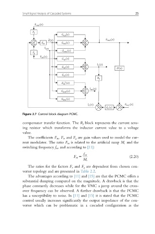
Figure 2.7 Control block diagram PCMC.
compensator transfer function. The R f block represents the current sens-
ing resistor which transforms the inductor current value to a voltage
value.
The coefficients F m , F v , and F g are gain values used to model the cur-
rent modulator. The ratio F m is related to the artificial ramp M c and the
switching frequency f sw and according to [11]:
f sw
F m 5 (2.20)
M c
The ratios for the factors F v and F g are dependent from chosen con-
verter topology and are presented in Table 2.2.
The advantages according to [11] and [15] are that the PCMC offers a
substantial damping compared on the magnitude. A drawback is that the
phase constantly decreases while for the VMC a jump around the cross-
over frequency can be observed. A further drawback is that the PCMC
has a susceptibility to noise. In [11] and [15] it is stated that the PCMC
control usually increases significantly the output impedance of the con-
verter which can be problematic in a cascaded configuration as the