
Page 68 - Modern Control of DC-Based Power Systems
P. 68
Small-Signal Analysis of Cascaded Systems 33
converters are both represented by their switching model could lead to
different stability limits. Very often in the simplified analysis stiff DC
sources are considered and therefore no control loop interaction between
the different converters takes place.
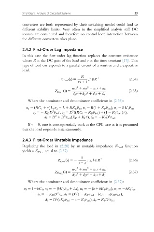
2.4.2 First-Order Lag Impedance
In this case the first-order lag function replaces the constant resistance
where R is the DC gain of the load and τ is the time constant [17]. This
type of load corresponds to a parallel circuit of a resistive and a capacitive
load.
R
Z Load sðÞ 5 ;τAR 1 (2.34)
τs 1 1
3 2
n 3 s 1 n 2 s 1 n 1 s 1 n 0
s ðÞ 5 (2.35)
Z IN CL 3 2
d 3 s 1d 2 s 1 d 1 s 1 d 0
Where the nominator and denominator coefficients in (2.35):
ÞL; n 2 5 L 1 RK D v in ; n 1 5 R 1 1 K P v in1 Þ; n 0 5 RK I v in ;
n 3 5 RC 1 1 τð ð
2 2 RC 1 2 K D v in1 Þ 1 1 2 K P v in1 ÞτÞ;
d 3 52 K D D v in τ; d 2 5 D ðð ð
2 2 2
Þ; d 0 52K I D v in1
d 1 5 D 1 D v in1 K P 1 K I τð
If τ 5 0, one is consequentially back at the CPL case as it is presumed
that the load responds instantaneously.
2.4.3 First-Order Unstable Impedance
Replacing the load in (2.28) by an unstable impedance Z Load function
equal to (2.37).
yields a Z IN CL
b
Z Load sðÞ 52 ;a; bAR 1 (2.36)
s 2 a
3 2
n 3 s 1 n 2 s 1 n 1 s 1 n 0
s ðÞ 5 (2.37)
3 2
Z IN CL
d 3 s 1 d 2 s 1 d 1 s 1 d 0
Where the nominator and denominator coefficients in (2.37):
Þ; n 1 52 b 1 bK P v in1 Þ; n 0 52bK I v in ;
n 3 5 12bC 1 ; n 2 52 bK D v in 1 Lað ð
2
2
d 3 52 K D D v in ; d 2 5 D 1 2 K P v in1 2bC 1 1 aK D v in1 Þ;
ð
2 2
d 1 5 D ðaK P v in1 2 a 2 K I v in1 Þ; d 0 5 K I D v in1