
Page 54 - Modern Control of DC-Based Power Systems
P. 54
Small-Signal Analysis of Cascaded Systems 19
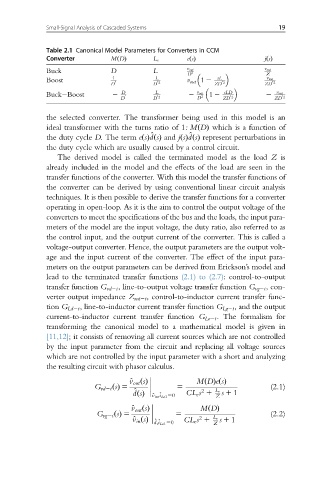
Table 2.1 Canonical Model Parameters for Converters in CCM
Converter MðDÞ L e eðsÞ jðsÞ
Buck D L v out v out
D 2 Z
Boost 1 L v out 1 2 sL v out
D 0 D 0 2 ZD 0 2 ZD 0 2
v out
Buck Boost 2 D L 0 2 2 D 2 1 2 sLD 0 2 2 v out 0 2
D 0 D ZD ZD
the selected converter. The transformer being used in this model is an
ideal transformer with the turns ratio of 1:MðDÞ which is a function of
^
^
the duty cycle D. The term eðsÞdðsÞ and jðsÞdðsÞ represent perturbations in
the duty cycle which are usually caused by a control circuit.
The derived model is called the terminated model as the load Z is
already included in the model and the effects of the load are seen in the
transfer functions of the converter. With this model the transfer functions of
the converter can be derived by using conventional linear circuit analysis
techniques. It is then possible to derive the transfer functions for a converter
operating in open-loop. As it is the aim to control the output voltage of the
converters to meet the specifications of the bus and the loads, the input para-
meters of the model are the input voltage, the duty ratio, also referred to as
the control input, and the output current of the converter. This is called a
voltage-output converter. Hence, the output parameters are the output volt-
age and the input current of the converter. The effect of the input para-
meters on the output parameters can be derived from Erickson’s model and
lead to the terminated transfer functions (2.1) to (2.7): control-to-output
transfer function G vd2t , line-to-output voltage transfer function G vg2t ,con-
verter output impedance Z out2t , control-to-inductor current transfer func-
tion G Ld2t , line-to-inductor current transfer function G Lg2t ,and theoutput
current-to-inductor current transfer function G Lo2t . The formalism for
transforming the canonical model to a mathematical model is given in
[11,12]; it consists of removing all current sources which are not controlled
by the input parameter from the circuit and replacing all voltage sources
which are not controlled by the input parameter with a short and analyzing
the resulting circuit with phasor calculus.
G vd2t ðsÞ 5 ^ v out ðsÞ 5 MDðÞeðsÞ (2.1)
^ CL e s 1 L e s 1 1
2
^ v in ; ^ i Lo1 50
dðsÞ Z
G vg2t ðsÞ 5 ^ v out ðsÞ 5 MDðÞ (2.2)
2
CL e s 1 L e
Z
^ v in ðsÞ ^ d; ^ i Lo1 50 s 1 1