
Page 53 - Modern Control of DC-Based Power Systems
P. 53
18 Modern Control of DC-Based Power Systems
behavior. The main goal is to determine under which circumstances the
ideal representation is meaningful and under which it may even produce
misleading results.
To be able to design the control system of the converter, it is necessary
to model its dynamic behavior. Typically this includes how the variations
of the input voltage, the load current, and the duty cycle affect the output
voltage. As converters are nonlinear components due to the switching
behavior, state-space averaging is often used to generate small-signal models.
The averaging of converter circuit over the two states of the switch provides
the equations of converter. This procedure neglects the switching ripple as it
is considered small in well-designed converters and therefore makes the more
important dynamics of the converters accessible. Because only small-signal
disturbances are analyzed the averaged model is linearized at the operating
point. The derivation of the linearized model via classic circuit analysis and
the more common approach via state-space averaging was presented by
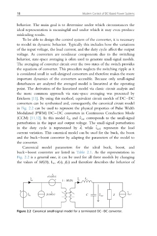
Erickson [11]. By using this method, equivalent circuit models of DC DC
converters can be synthesized and, consequently, the canonical circuit model
in Fig. 2.2 can be used to represent the physical properties of Pulse Width
Modulated (PWM) DC DC converters in Continuous Conduction Mode
(CCM) [11,12]. In this model ^v in and ^v out corresponds to the small-signal
perturbation in the input and output voltage. The small-signal perturbation
^
in the duty cycle is represented by d,while ^ i Lo1 represents the load
current variation. This canonical model can be used for the buck, the boost
and the buck boost converter by adapting the parameters of the model to
the converter.
Canonical model parameters for the ideal buck, boost, and
buck boost converter are listed in Table 2.1. As the representation in
Fig. 2.2 is a general one, it can be used for all three models by changing
the values of MðDÞ,L e , eðsÞ, jðsÞ and therefore describes the behavior of
^
e(s)d(s)
^ ^ L e
i in 1 : M(D) i L
^ ^
^ j(s)d(s) C ^ Z i Lo1
v in v out
Figure 2.2 Canonical small-signal model for a terminated DC DC converter.