
Page 107 - Modern Optical Engineering The Design of Optical Systems
P. 107
90 Chapter Five
the same proportion. Thus if the simple lens used as the example in
Sec. 5.4 were increased in focal length to 200 mm, its aperture
increased to 20 mm, and the field coverage increased to 120 mm, then
the aberrations would all be doubled. Note, however, that the speed, or
f/number, would remain at f/10 and the angular coverage would
remain at 17 . The percentage distortion would not be changed, nor
would the chromatic difference of magnification (CDM).
Aberrations are occasionally expressed as angular aberrations. For
example, the transverse spherical aberration of a system subtends an
angle from the second principal point of the system; this angle is the
angular spherical aberration. Note that the angular aberrations are
not changed by scaling the size of the optical system.
5.6 Optical Path Difference (Wave Front
Aberration)
Aberrations can also be described in terms of the wave nature of light.
In Chap. 1, it was pointed out that the light waves converging to form
a “perfect” image would be spherical in shape. Thus when aberrations
are present in a lens system, the waves converging on an image point
are deformed from the ideal shape (which is a sphere centered on the
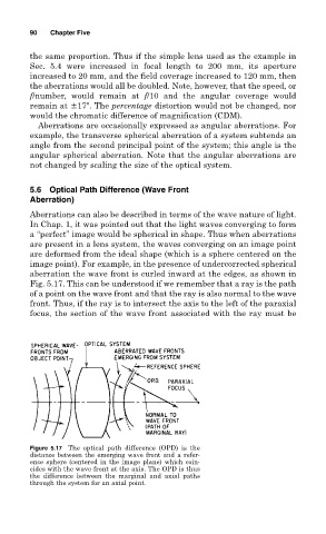
image point). For example, in the presence of undercorrected spherical
aberration the wave front is curled inward at the edges, as shown in
Fig. 5.17. This can be understood if we remember that a ray is the path
of a point on the wave front and that the ray is also normal to the wave
front. Thus, if the ray is to intersect the axis to the left of the paraxial
focus, the section of the wave front associated with the ray must be
Figure 5.17 The optical path difference (OPD) is the
distance between the emerging wave front and a refer-
ence sphere (centered in the image plane) which coin-
cides with the wave front at the axis. The OPD is thus
the difference between the marginal and axial paths
through the system for an axial point.