
Page 112 - Modern Optical Engineering The Design of Optical Systems
P. 112
The Primary Aberrations 95
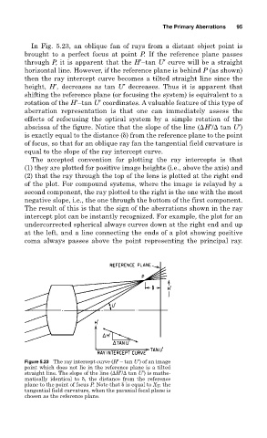
In Fig. 5.23, an oblique fan of rays from a distant object point is
brought to a perfect focus at point P. If the reference plane passes
through P, it is apparent that the H′–tan U′ curve will be a straight
horizontal line. However, if the reference plane is behind P (as shown)
then the ray intercept curve becomes a tilted straight line since the
height, H′, decreases as tan U′ decreases. Thus it is apparent that
shifting the reference plane (or focusing the system) is equivalent to a
rotation of the H′–tan U′ coordinates. A valuable feature of this type of
aberration representation is that one can immediately assess the
effects of refocusing the optical system by a simple rotation of the
abscissa of the figure. Notice that the slope of the line (
H′/
tan U′)
is exactly equal to the distance ( ) from the reference plane to the point
of focus, so that for an oblique ray fan the tangential field curvature is
equal to the slope of the ray intercept curve.
The accepted convention for plotting the ray intercepts is that
(1) they are plotted for positive image heights (i.e., above the axis) and
(2) that the ray through the top of the lens is plotted at the right end
of the plot. For compound systems, where the image is relayed by a
second component, the ray plotted to the right is the one with the most
negative slope, i.e., the one through the bottom of the first component.
The result of this is that the sign of the aberrations shown in the ray
intercept plot can be instantly recognized. For example, the plot for an
undercorrected spherical always curves down at the right end and up
at the left, and a line connecting the ends of a plot showing positive
coma always passes above the point representing the principal ray.
Figure 5.23 The ray intercept curve (H′ – tan U′) of an image
point which does not lie in the reference plane is a tilted
straight line. The slope of the line (
H′/
tan U′) is mathe-
matically identical to , the distance from the reference
plane to the point of focus P. Note that is equal to X T , the
tangential field curvature, when the paraxial focal plane is
chosen as the reference plane.