
Page 117 - Modern Optical Engineering The Design of Optical Systems
P. 117
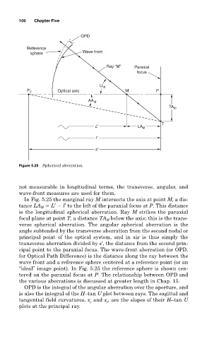
100   Chapter Five

                                OPD

           Reference
             sphere              Wave front


                                          Ray “M”    Paraxial
                                                      focus

                                       U M
           P 2         Optical axis              M           P
                                   AA M
                                                                  TA M


                                      L′              LA M     T
                                      l ′

                                      s′


        Figure 5.25 Spherical aberration.


        not measurable in longitudinal terms, the transverse, angular, and
        wave-front measures are used for them.
          In Fig. 5.25 the marginal ray M intersects the axis at point M, a dis-
        tance LA M   L′   l′ to the left of the paraxial focus at P. This distance
        is the longitudinal spherical aberration. Ray M strikes the paraxial
        focal plane at point T, a distance TA M below the axis; this is the trans-
        verse spherical aberration. The angular spherical aberration is the
        angle subtended by the transverse aberration from the second nodal or
        principal point of the optical system, and in air is thus simply the
        transverse aberration divided by s′, the distance from the second prin-
        cipal point to the paraxial focus. The wave-front aberration (or OPD,
        for Optical Path Difference) is the distance along the ray between the
        wave front and a reference sphere centered at a reference point (or an
        “ideal” image point). In Fig. 5.25 the reference sphere is shown cen-
        tered on the paraxial focus at P. The relationship between OPD and
        the various aberrations is discussed at greater length in Chap. 15.
          OPD is the integral of the angular aberration over the aperture, and
        is also the integral of the H–tan U plot between rays. The sagittal and
        tangential field curvatures, x and x , are the slopes of their H–tan U
                                    s     t
        plots at the principal ray.