Page 120 - Modern Optical Engineering The Design of Optical Systems
P. 120

The Primary Aberrations  103


                           R


                       R       R
                           R                   COMA T

                                       (COMA − R)
                                            T
                                           2R
                           R


                           60°


         COMA T                         LOCUS of
                                        marginal zone rays


                                        LOCUS of
                                        0.707 zone rays

                                        LOCUS of
               COMA S                   0.50 zone rays


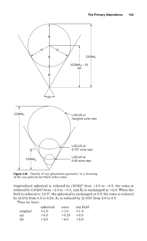
        Figure 5.26 Details of ray placement geometry in a drawing
        of the ray pattern for third order coma.

                                             2
        longitudinal spherical is reduced by (10/20) from  2.0 to  0.5; the coma is
                       2
        reduced by (10/20) from  2.0 to  0.5, and X T is unchanged at  2.0. When the
        field is reduced to  2.5 , the spherical is unchanged at 0.5; the coma is reduced
                                                  2
        by (2.5/5) from 0.5 to 0.25; X T is reduced by (2.5/5) from 2.0 to 0.5.
          Thus we have:
                       spherical  coma    tan field
            original    1.0        1.0     1.0
            (a)         0.5        0.25    0.5
            (b)         2.0        4.0     2.0
   115   116   117   118   119   120   121   122   123   124   125