
Page 125 - Modern Optical Engineering The Design of Optical Systems
P. 125
108 Chapter Six
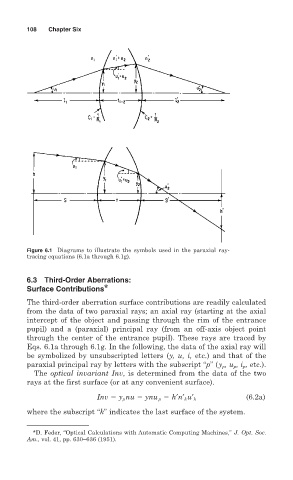
Figure 6.1 Diagrams to illustrate the symbols used in the paraxial ray-
tracing equations (6.1a through 6.1g).
6.3 Third-Order Aberrations:
Surface Contributions *
The third-order aberration surface contributions are readily calculated
from the data of two paraxial rays; an axial ray (starting at the axial
intercept of the object and passing through the rim of the entrance
pupil) and a (paraxial) principal ray (from an off-axis object point
through the center of the entrance pupil). These rays are traced by
Eqs. 6.1a through 6.1g. In the following, the data of the axial ray will
be symbolized by unsubscripted letters (y, u, i, etc.) and that of the
paraxial principal ray by letters with the subscript “p” (y p , u p , i p , etc.).
The optical invariant Inv, is determined from the data of the two
rays at the first surface (or at any convenient surface).
(6.2a)
Inv y p nu ynu p h′n′ k u′ k
where the subscript “k” indicates the last surface of the system.
*D. Feder, “Optical Calculations with Automatic Computing Machines,” J. Opt. Soc.
Am., vol. 41, pp. 630–636 (1951).