
Page 124 - Modern Optical Engineering The Design of Optical Systems
P. 124
Third-Order Aberration Theory and Calculation 107
6.2 Paraxial Raytracing
Although the paraxial raytracing equations were presented in Chap. 3,
they are repeated here for completeness (in slightly modified form).
Opening: 1. Given y and u at the first surface
or 2. y lu (6.1a)
or 3. y h su (6.1b)
Refraction:
nu cy(n′ n)
u′ (6.1c)
n′ n′
Transfer to the next surface:
(6.1d)
y j 1 y j tu′ j
(6.1e)
u j 1 u′ j
Closing:
y k
l′ k (6.1f)
u′ k
or
(6.1g)
h′ y k s′ k u′ k
The symbols have the following meanings:
y The height at which a ray strikes the surface; positive above the
axis, negative below.
u(u′) The slope of the ray before (after) refraction.
h(h′) The height of the ray in the object (image) plane; positive above the
axis, negative below.
l(l′) The intersection distance from the surface before (after) refraction; posi-
tive (negative) if the intercept point is to the right (left) of the surface.
s(s′) The distance from the first (last) surface to the object (image) plane;
positive (negative) if the plane is to the right (left) of the surface.
c The curvature (reciprocal radius) of the surface, equal to 1/R; posi-
tive if the center of curvature is to the right of the surface, negative
if to the left.
n(n′) The index of refraction preceding (following) the surface; positive if
the ray travels from left to right, negative if it travels right to left.
The vertex spacing between surfaces (j) and ( j 1); positive if sur-
t j
face ( j 1) is to the right of surface (j).
k A subscript indicating the last surface of the system.
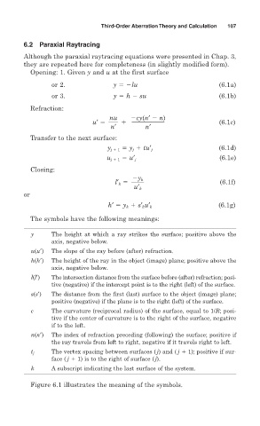
Figure 6.1 illustrates the meaning of the symbols.