Page 126 - Modern Optical Engineering The Design of Optical Systems
P. 126

Third-Order Aberration Theory and Calculation  109

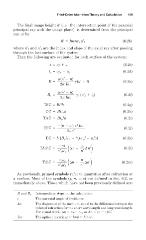
          The final image height h′ (i.e., the intersection point of the paraxial
        principal ray with the image plane), is determined from the principal
        ray, or by

                                                                    (6.2b)
                                  h′   Inv/n′ k u′ k
        where n′ k and u′ k are the index and slope of the axial ray after passing
        through the last surface of the system.
          Then the following are evaluated for each surface of the system:

                            i   cy   u                              (6.2c)
                                                                    (6.2d)
                            i p   cy p   u p
                                 n(n′   n)
                           B              y(u′   i)                 (6.2e)
                                  2n′Inv

                                 n(n′   n)
                           B p            y p (u′ p   i p )         (6.2f)
                                  2n′Inv
                                  2
                         TSC   Bi h                                 (6.2g)
                          CC   Bii p h                              (6.2h)
                                   2
                        TAC   Bi p h                                (6.2i)
                                 (n   n′) chInv
                         TPC                                        (6.2j)
                                      2nn′
                                               2
                                                    2
                                          1
                          DC   h [B p ii p   
 (u′ p   u p )]       (6.2k)
                                           2
                                  yi         n
                       TAchC            
n     
n′                  (6.2l)
                                n′ k u′ k    n′
                                             n  
n′
                                  yi p
                        TchC           
n                          (6.2m)
                                             n′
                                n′ k u′ k
          As previously, primed symbols refer to quantities after refraction at
        a surface. Most of the symbols (y, n, u, c) are defined in Sec. 6.2, or
        immediately above. Those which have not been previously defined are:


          B and B p  Intermediate steps in the calculation.
          i         The paraxial angle of incidence.
          
n        The dispersion of the medium, equal to the difference between the
                    index of refraction for the short wavelength and long wavelength.
                    For visual work, 
n   n F    n C , or 
n   (n   1)/V.
          Inv       The optical invariant   hnu   h′n′u′.
   121   122   123   124   125   126   127   128   129   130   131