
Page 169 - Modern Optical Engineering The Design of Optical Systems
P. 169
152 Chapter Seven
advised to keep first trials of this type as simple and uncomplicated as
possible. Further, the reduction of the system to practice is much
simplified if compound angles are avoided. If our problem had required
that the final image be rotated 45°, then we would necessarily have
had to depart from the cartesian planes to achieve the desired result.
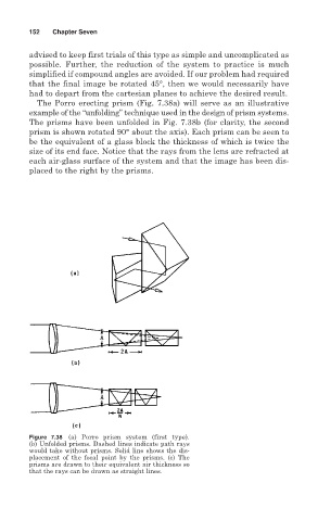
The Porro erecting prism (Fig. 7.38a) will serve as an illustrative
example of the “unfolding” technique used in the design of prism systems.
The prisms have been unfolded in Fig. 7.38b (for clarity, the second
prism is shown rotated 90° about the axis). Each prism can be seen to
be the equivalent of a glass block the thickness of which is twice the
size of its end face. Notice that the rays from the lens are refracted at
each air-glass surface of the system and that the image has been dis-
placed to the right by the prisms.
Figure 7.38 (a) Porro prism system (first type).
(b) Unfolded prisms. Dashed lines indicate path rays
would take without prisms. Solid line shows the dis-
placement of the focal point by the prisms. (c) The
prisms are drawn to their equivalent air thickness so
that the rays can be drawn as straight lines.