
Page 170 - Modern Optical Engineering The Design of Optical Systems
P. 170
Prism and Mirror Systems 153
In Fig. 7.38c, the prisms are drawn with their “equivalent air thick-
ness” as discussed in Sec. 7.8. This allows us to draw the (paraxial) light
rays through the prism as straight lines, simplifying the construction
considerably.
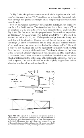
Now let us suppose that we are to design the minimum size Porro sys-
tem for a 7 50 binocular. The objective lens has a focal length of 7 in,
5
an aperture of 2 in, and is to cover a
-in-diameter field, as sketched in
8
Fig. 7.39a. We first note that the proportions of face width to “equivalent
air thickness” for each prism (Fig. 7.39a) are A:2A/n 1:2/n, or, if we
assume an index of 1.50, 3:4. We begin the design from the image and
1
work toward the objective. Placing the exit face of the prism
in from
2
the image (to allow for clearance and to keep the glass surface well out
of the focal plane), we construct the dashed line shown in Fig. 7.39a with
a slope of 3:8 (one-half the face-to-equivalent-thickness ratio) starting
from the axial intercept of the exit face. This line is, of course, the locus
of the corners of a family of prisms of various sizes, and the point where
it intersects the extreme clearance ray defines the minimum size prism
which will transmit the entire cone of light from the objective. For prac-
tical purposes, the prism should be made slightly larger than this to
allow for bevels and mounting shoulders.
Figure 7.39 The layout of a minimum-size prism system is
shown in (a). The extreme clearance rays connect the rim of
the objective with the edge of the field of view. The intersection
of the dashed lines (see text) with these rays locates the corner
of the smallest prism which will pass the full image cone. In (b)
the prisms are drawn to scale, showing their true thickness.