
Page 167 - Modern Optical Engineering The Design of Optical Systems
P. 167
150 Chapter Seven
accomplished by straightforward trial and error. A rough perspective
sketch is made to indicate the reflections necessary to locate the image
in its desired position. The orientation of the image is then checked by
the technique of Sec. 7.7; reflectors are added in various orientations
until the image orientation is correct. Usually several roughly equiva-
lent schemes are possible, and a selection can be made based on the
requirements of the application.
When the reflection system is completed, the optical system is
unfolded, i.e., sketched with the optical axis as a straight line. The object,
image, and lens apertures are added to the sketch and the necessary
sizes for the reflectors are determined in both meridians. If the system
is to be composed of prisms, the unfolded layout is repeated with the
axial distances adjusted to the “equivalent air thickness” (t/n) for that
portion of the system which is glass so that the ray paths can be drawn
as straight lines.
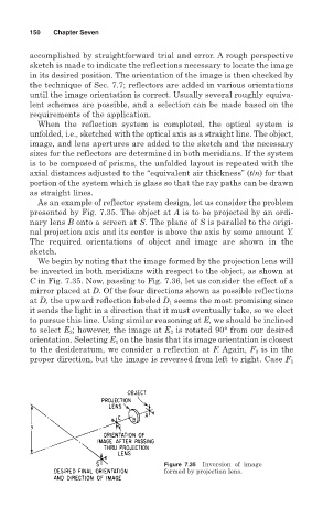
As an example of reflector system design, let us consider the problem
presented by Fig. 7.35. The object at A is to be projected by an ordi-
nary lens B onto a screen at S. The plane of S is parallel to the origi-
nal projection axis and its center is above the axis by some amount Y.
The required orientations of object and image are shown in the
sketch.
We begin by noting that the image formed by the projection lens will
be inverted in both meridians with respect to the object, as shown at
C in Fig. 7.35. Now, passing to Fig. 7.36, let us consider the effect of a
mirror placed at D. Of the four directions shown as possible reflections
at D, the upward reflection labeled D 1 seems the most promising since
it sends the light in a direction that it must eventually take, so we elect
to pursue this line. Using similar reasoning at E, we should be inclined
to select E 2 ; however, the image at E 2 is rotated 90° from our desired
orientation. Selecting E 1 on the basis that its image orientation is closest
to the desideratum, we consider a reflection at F. Again, F 3 is in the
proper direction, but the image is reversed from left to right. Case F 1
Figure 7.35 Inversion of image
formed by projection lens.