
Page 165 - Modern Optical Engineering The Design of Optical Systems
P. 165
148 Chapter Seven
Figure 7.32 45 tilting eyepiece
prism.
Figure 7.32 shows a prism which is often used in microscope eye-
pieces to change the direction of the line of sight from vertical to a
more-convenient-to-use 45°. As shown, the prism can be used as
a beamsplitter either to provide for coaxial illumination or to allow a
second eyepiece; without the beamsplitting feature, it simply redirects
the line of sight.
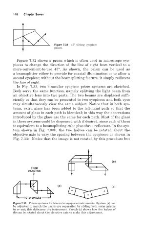
In Fig. 7.33, two binocular eyepiece prism systems are sketched.
Both serve the same function, namely splitting the light beam from
an objective lens into two parts. The two beams are displaced suffi-
ciently so that they can be presented to two eyepieces and both eyes
may simultaneously view the same subject. Notice that in both sys-
tems, extra glass has been added to the left-hand path so that the
amount of glass in each path is identical; in this way the aberrations
introduced by the glass are the same for each path. Most of the glass
in these systems could be dispensed with if desired, since each of them
is equivalent to a beamsplitting cube plus three reflectors. In the sys-
tem shown in Fig. 7.33b, the two halves can be rotated about the
objective axis to vary the spacing between the eyepieces as shown in
Fig. 7.33c. Notice that the image is not rotated by this procedure but
Figure 7.33 Prism systems for binocular eyepiece instruments. System (a) can
be adjusted to match the user’s eye separation by sliding both outer prisms
in or out; this defocuses the instrument. Sketch (c) shows how the halves of
(b) can be rotated about the objective axis to make this adjustment.