
Page 198 - Modern Optical Engineering The Design of Optical Systems
P. 198
Stops, Apertures, Pupils and Diffraction 181
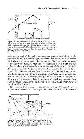
Figure 9.6 Stray (undesired) radiation from outside the use-
ful field of this simple radiometer can be reflected from the
inner walls of the housing and degrade the function of the
system. Sharp-edged baffles, shown in the lower portion, trap
this radiation and prevent the detector from “seeing” a
directly illuminated surface.
obstructing part of the radiation from the desired field of view. The
dashed line AA′ is a “line of sight” from the detector to the point on the
wall where the extraneous radiation begins. The first baffle is erected
to the intersection of AA′ with the dotted clearance line. Solid line BB′
indicates the path of stray light from the top of the lens to the wall.
The area from baffle #1 to B′ is thus shadowed and “safe” for the detec-
tor to “see.” The dashed line from B′ to A is thus the safe line of sight,
and baffle #2 located at the intersection of AB′ and the clearance line
will prevent the detector from “seeing” the illuminated wall beyond B′.
This procedure is repeated until the entire side wall is protected. Note
that the inside edges of the baffles should be sharp and their surfaces
rough and blackened.
The cast and machined baffles shown in Fig. 9.6 are obviously
expensive to fabricate. Less expensive alternatives include washers
Figure 9.7 Construction for the systematic layout of baf-
fles. Note that baffle #3 shields the wall back to point D;
thus, all three baffles could be shifted forward some-
what, so that their coverages overlap.