
Page 195 - Modern Optical Engineering The Design of Optical Systems
P. 195
178 Chapter Nine
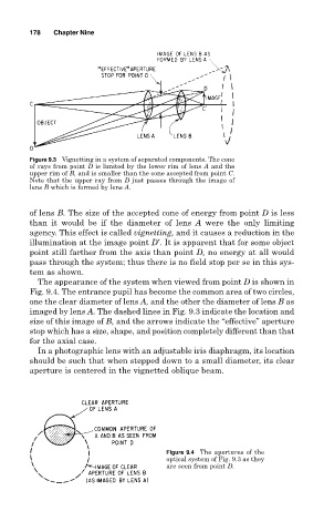
Figure 9.3 Vignetting in a system of separated components. The cone
of rays from point D is limited by the lower rim of lens A and the
upper rim of B, and is smaller than the cone accepted from point C.
Note that the upper ray from D just passes through the image of
lens B which is formed by lens A.
of lens B. The size of the accepted cone of energy from point D is less
than it would be if the diameter of lens A were the only limiting
agency. This effect is called vignetting, and it causes a reduction in the
illumination at the image point D′. It is apparent that for some object
point still farther from the axis than point D, no energy at all would
pass through the system; thus there is no field stop per se in this sys-
tem as shown.
The appearance of the system when viewed from point D is shown in
Fig. 9.4. The entrance pupil has become the common area of two circles,
one the clear diameter of lens A, and the other the diameter of lens B as
imaged by lens A. The dashed lines in Fig. 9.3 indicate the location and
size of this image of B, and the arrows indicate the “effective” aperture
stop which has a size, shape, and position completely different than that
for the axial case.
In a photographic lens with an adjustable iris diaphragm, its location
should be such that when stepped down to a small diameter, its clear
aperture is centered in the vignetted oblique beam.
Figure 9.4 The apertures of the
optical system of Fig. 9.3 as they
are seen from point D.