
Page 196 - Modern Optical Engineering The Design of Optical Systems
P. 196
Stops, Apertures, Pupils and Diffraction 179
The determination of vignetting in an optical system can be accom-
plished by tracing just two paraxial rays. Begin by collecting the powers,
spaces, and clear apertures of the system. Then trace an axial paraxial
ray from the foot of the object with a height of 1.0 at the first element.
Calculate y/ca for each element and aperture; the diameter with the
largest y/ca is the aperture stop. Multiply the raytrace data (y and u)
by ca/y to get the raytrace data of the marginal ray. Trace an oblique
ray through the center of the aperture stop at a convenient slope, say
/ca for each element and aperture. The one with the
0.1. Calculate y p
largest value is the field stop. Scale the ray data by ca/y to get the
p
data of the principal ray. The intersection of this ray with the object and
image planes gives the size of the field. The two rays can be combined
as described in Sec. 4.2 to obtain the data of any third ray, without exe-
cuting another raytrace. Of course the upper and lower rim ray data is
simply (y y) and (u u). If the ray height exceeds the clear aper-
p
p
ture, vignetting occurs. The amount of vignetting is indicated by what
fraction of the axial ray height will create a height which does not
exceed the clear aperture when combined with the principal ray
height.
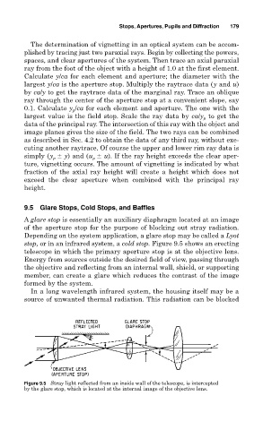
9.5 Glare Stops, Cold Stops, and Baffles
A glare stop is essentially an auxiliary diaphragm located at an image
of the aperture stop for the purpose of blocking out stray radiation.
Depending on the system application, a glare stop may be called a Lyot
stop, or in an infrared system, a cold stop. Figure 9.5 shows an erecting
telescope in which the primary aperture stop is at the objective lens.
Energy from sources outside the desired field of view, passing through
the objective and reflecting from an internal wall, shield, or supporting
member, can create a glare which reduces the contrast of the image
formed by the system.
In a long wavelength infrared system, the housing itself may be a
source of unwanted thermal radiation. This radiation can be blocked
Figure 9.5 Stray light reflected from an inside wall of the telescope, is intercepted
by the glare stop, which is located at the internal image of the objective lens.