
Page 199 - Modern Optical Engineering The Design of Optical Systems
P. 199
182 Chapter Nine
constrained between spacers, or stamped, cup-shaped washers which
can be cemented or press-fitted into place. This type of baffling is not
necessary in all cases. Frequently, internal scattering can be suffi-
ciently reduced by scoring or threading the offending internal surfaces
of the mount. In this way, the reflections are broken up and scattered,
reducing the amount of reflection and destroying any glare images.
The use of a flat black paint is also highly advisable, although care
must be taken to be sure that the paint remains both matte and black
at near-grazing angles of incidence and at the application wavelength.
Some black paints are light grey in the IR. Sandblasting to roughen
the surface and blackening (for aluminum, black anodizing works well)
is a simple and usually effective treatment. Another treatment is the
application of black “flocked” paper. This can be procured in rolls, cut
to size, and cemented to the offending surfaces; this is especially
useful for large internal surfaces and for laboratory equipment. The
source of glare light can be indentified by placing the eye at a location
in the image which should be dark and looking back into the optics.
For a projection system place the eye just outside the field.
Specialized flat black paints are available for specific applications
and wavelengths. In the absence of special paints, Floquil brand flat
black model locomotive paint usually can be found at the local hobby
shop and makes a pretty good general-purpose flat black. A specialized
anodizing process, Martin Optical Black (or Martin Infrablack for the
infrared) is extremely effective ( 0.2 percent reflective) but is very
fragile.
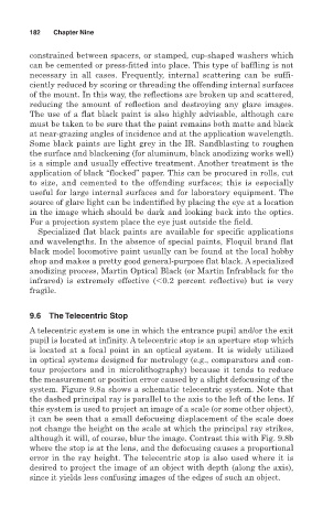
9.6 The Telecentric Stop
A telecentric system is one in which the entrance pupil and/or the exit
pupil is located at infinity. A telecentric stop is an aperture stop which
is located at a focal point in an optical system. It is widely utilized
in optical systems designed for metrology (e.g., comparators and con-
tour projectors and in microlithography) because it tends to reduce
the measurement or position error caused by a slight defocusing of the
system. Figure 9.8a shows a schematic telecentric system. Note that
the dashed principal ray is parallel to the axis to the left of the lens. If
this system is used to project an image of a scale (or some other object),
it can be seen that a small defocusing displacement of the scale does
not change the height on the scale at which the principal ray strikes,
although it will, of course, blur the image. Contrast this with Fig. 9.8b
where the stop is at the lens, and the defocusing causes a proportional
error in the ray height. The telecentric stop is also used where it is
desired to project the image of an object with depth (along the axis),
since it yields less confusing images of the edges of such an object.