
Page 323 - Modern Optical Engineering The Design of Optical Systems
P. 323
302 Chapter Thirteen
value for f o upon which to base our solution. There are a number of cri-
teria by which to judge the value of a given solution. In general, one
desires to minimize the power of the components in any given system;
in subsequent chapters, it will become apparent that it is often advis-
2
able to minimize one or all of the following: | |, |y |, |y |
(where the symbol |x| indicates the absolute value of x), is the com-
ponent power, and y represents the height of either the axial or princi-
pal ray on the component, or the element semiclear aperture.
Avoiding, for a few chapters at least, the rationale behind these
desiderata, we shall proceed to indicate the technique. For a number
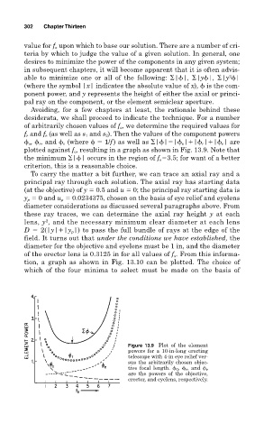
of arbitrarily chosen values of f o , we determine the required values for
f r and f e (as well as s 1 and s 2 ). Then the values of the component powers
o , r , and e (where 1/f ) as well as | | | o | | r | | e | are
plotted against f o , resulting in a graph as shown in Fig. 13.9. Note that
the minimum | | occurs in the region of f o 3.5; for want of a better
criterion, this is a reasonable choice.
To carry the matter a bit further, we can trace an axial ray and a
principal ray through each solution. The axial ray has starting data
(at the objective) of y 0.5 and u 0; the principal ray starting data is
y p 0 and u p 0.0234375, chosen on the basis of eye relief and eyelens
diameter considerations as discussed several paragraphs above. From
these ray traces, we can determine the axial ray height y at each
lens, y , and the necessary minimum clear diameter at each lens
2
D 2(|y| |y p |) to pass the full bundle of rays at the edge of the
field. It turns out that under the conditions we have established, the
diameter for the objective and eyelens must be 1 in, and the diameter
of the erector lens is 0.3125 in for all values of f o . From this informa-
tion, a graph as shown in Fig. 13.10 can be plotted. The choice of
which of the four minima to select must be made on the basis of
Figure 13.9 Plot of the element
powers for a 10-in-long erecting
telescope with 4-in eye relief ver-
sus the arbitrarily chosen objec-
tive focal length. 0 , r , and e
are the powers of the objective,
erector, and eyelens, respectively.