
Page 328 - Modern Optical Engineering The Design of Optical Systems
P. 328
Optical System Layout 307
aperture in this regard, microscope objectives are usually specified by
power and numerical aperture; for example, a 16-mm objective is usually
listed as a 10 NA 0.25.
At a distance of 10 in, the visual resolution of one minute of arc
(0.0003 radians) corresponds to a linear resolution of about 0.003 in, or
0.076 mm. When the object is magnified by an optical system, the visual
resolution at the object is thus
0.003 in 0.076 mm
R (13.14)
MP MP
If we now equate the visual resolution R with the diffraction limit Z
and solve for the magnification, we find that
0.12 NA
MP (13.15)
with in millimeters, is the magnifcation at which the diffraction limit
and visual limit match. At this power the eye can resolve all the detail
present in the image, and setting 0.55 m, any magnification
beyond 225 NA is “empty magnification.” However, as with telescopes,
magnifications several times this amount are regularly used, as
discussed in Sec. 13.3.
13.6 Rangefinders
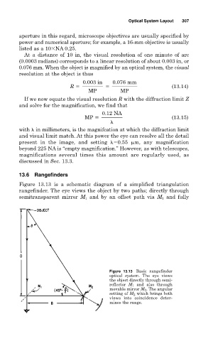
Figure 13.13 is a schematic diagram of a simplified triangulation
rangefinder. The eye views the object by two paths; directly through
semitransparent mirror M 1 and by an offset path via M 1 and fully
Figure 13.13 Basic rangefinder
optical system. The eye views
the object directly through semi-
reflector M 1 and also through
movable mirror M 2 . The angular
setting of M 2 which brings both
views into coincidence deter-
mines the range.