
Page 333 - Modern Optical Engineering The Design of Optical Systems
P. 333
312 Chapter Thirteen
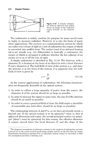
Figure 13.16 A simple radiome-
ter with an objective lens which
forms an image of the radiation
source directly on the detector
cell.
The radiometer is widely used for the purpose its name would seem
to imply, to measure radiation. However, it is also the basis of many
other applications. The receiver in a communications system by which
one talks over a beam of light is a sort of radiometer the output of which
is converted into audible form. The seeker head of an infrared homing
air-to-air missile (e.g., the Sidewinder) is basically a radiometer the
output of which is arranged to indicate whether the hot exhaust of an
enemy jet is on or off the line of sight.
A simple radiometer is sketched in Fig. 13.16. The detector, with a
diameter D, is located at the focus of an objective with a focal distance
F and a diameter A. The half-field of view of the system is , and since
the detector is at the focus of the system, it is apparent that the half-
field of view is given by
D
(13.19)
2F
In the various applications of radiometers, the following characteri-
stics are frequently desirable in the optical system
1. In order to collect a large quantity of power from the source, the
diameter A of the system should be as large as possible.
2. In order to increase the signal-to-noise ratio, the size D of the detector
should be as small as possible.
3. In order to cover a practical field of view, the field angle should be
of reasonable size (and often, should be as large as possible).
The relationship between A and F is, as we have previously noted, a
limited one. If the optical system is to be aplanatic* (that is, free of
spherical aberration and coma), the second principal surface (or princi-
pal “plane”) must be spherical; for this reason, the effective diameter
A cannot exceed twice the focal distance F, and the slope of the
* The frequent assumption of aplanatic systems in the analysis of radiometric systems
is based (1) on the usual need for good image quality and (2) on the fact that the image
illumination (irradiance) produced by an aplanatic system cannot be exceeded, so that
the assumption provides a limiting case.