
Page 330 - Modern Optical Engineering The Design of Optical Systems
P. 330
Optical System Layout 309
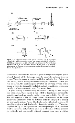
Figure 13.14 Typical rangefinder optical devices. (a) A telescopic
rangefinder with coincidence prism and penta-prism end reflectors.
(b) Sliding prism used at X to establish coincidence. (c) Pair of sliding
prisms used at X. (d) Rotating parallel plate used at X. Optical
micrometer. (e) Counter-rotating prisms used at Y to establish coinci-
dence. Risley prisms.
telescope is built into the system to provide magnification; the power
of each branch of the telescope must be carefully matched to avoid
errors. The coincidence prism is provided to split the field of view into
two halves, with a sharply focused dividing line between. In the sys-
tem as shown, the final image is inverted; an erecting system, either
prism or lens, is frequently included. Actual coincidence prisms are
usually much more complex than that shown here.
A great variety of devices may be utilized to bring the two images
into coincidence. Those shown in Fig. 13.14b to d are located between the
objective and eyelens, usually in the region marked X in Fig. 13.14a.
The sliding prism of Fig. 13.14b produces a displacement at the image
plane which increases with its distance from the image; it is usually
an achromatic prism. Figure 13.14c shows two identical prisms with
variable spacing, which displace but do not deviate the rays. The rotat-
ing block in Fig. 13.14d operates on the same principle. All of the above
tend to introduce astigmatism (that is, a difference of focal position
in vertically and horizontally aligned images) since they are tilted