
Page 335 - Modern Optical Engineering The Design of Optical Systems
P. 335
314 Chapter Thirteen
and the absolute maximum total field (0.016 radians) is a little less
than one degree (0.01745 radians). An immersion lens at the detector
(described below) with an index n′ would increase the maximum field
angle to 0.016n′.
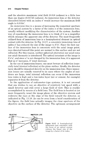
An immersion lens is a means of increasing the numerical aperture
of an optical system by a factor of the index n of the immersion lens,
usually without modifying the characteristics of the system. Another
way of considering the immersion lens is to think of it as a magnifier
which enlarges the apparent size of the detector. The most frequently
utilized form of immersion lens is a hemispherical element in optical
contact with the detector. In Fig. 13.17, a concentric immersion lens of
index n′ has reduced the size of the image to h′/n′. Since the first sur-
face of the immersion lens is concentric with the axial image point,
rays directed toward this point are normal to this surface and are not
refracted. For this reason, neither spherical aberration nor axial coma
nor axial chromatic is introduced. The optical invariant at the image is
h′n′u′, and since u′ is not changed by the immersion lens, it is apparent
that as n′ increases, h′ must decrease.
In the use of immersion lenses, one must beware of reflection (espe-
cially total internal reflection) at the plane surface. Ideally, the detector
layer should be deposited directly on the immersion lens. Since immer-
sion lenses are usually resorted to in cases where the angles of inci-
dence are large, total internal reflection can occur if the immersion
lens index is high and a low-index layer (air or cement, for example)
separates it from the detector.
In the application of radiometer-type systems, it is not unusual
that one wishes to use an objective of relatively low speed with a
small detector and still cover a large field of view. This is readily
accomplished by means of a field lens. The field lens is located at (or
more frequently, near) the image plane of the objective system and
redirects the rays at the edge of the field toward the detector, as
indicated in Fig. 13.18. As can be seen from a brief consideration of
the figure, the field lens actually images the clear aperture of the
objective on the surface of the detector. The optimum arrangement
Figure 13.17 A hemispherical
immersion lens concentric with
the focus of an optical system
reduces the linear size of the
image by a factor of its index.