
Page 338 - Modern Optical Engineering The Design of Optical Systems
P. 338
Optical System Layout 317
If one were to look into the large end of a pyramidal light pipe, one
would see a sort of checkerboard multiple image of the exit face (or
detector), as indicated in Fig. 13.20 for a two-dimensional case. The
checkerboard is wrapped around a sphere centered on the apex of the
pyramidal pipe. This image is, of course, the effective size of the (“mag-
nified”) detector, and the cone of light from the objective, as indicated by
rays A and A′ is spread out over this array. This effect is occasionally
useful in decorrelating the point-for-point relationship between the
detector surface and the objective aperture which is established when a
field lens is used. The effect is even more pronounced in a conical pipe.
The discussion in this section has been devoted to condensing radia-
tion on to a small detector. The tables can be turned. If we replace the
detector with a small source of radiation, devices such as field lenses
and light pipes can be used to increase the apparent size of the source
and to reduce the angle through which it radiates (or vice versa).
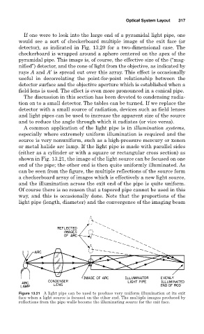
A common application of the light pipe is in illumination systems,
especially where extremely uniform illumination is required and the
source is very nonuniform, such as a high-pressure mercury or xenon
or metal halide arc lamp. If the light pipe is made with parallel sides
(either as a cylinder or with a square or rectangular cross section) as
shown in Fig. 13.21, the image of the light source can be focused on one
end of the pipe; the other end is then quite uniformly illuminated. As
can be seen from the figure, the multiple reflections of the source form
a checkerboard array of images which is effectively a new light source,
and the illumination across the exit end of the pipe is quite uniform.
Of course there is no reason that a tapered pipe cannot be used in this
way, and this is occasionally done. Note that the proportions of the
light pipe (length, diameter) and the convergence of the imaging beam
Figure 13.21 A light pipe can be used to produce very uniform illumination at its exit
face when a light source is focused on the other end. The multiple images produced by
reflections from the pipe walls become the illuminating source for the exit face.