
Page 337 - Modern Optical Engineering The Design of Optical Systems
P. 337
316 Chapter Thirteen
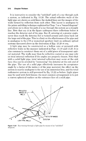
It is instructive to consider the “unfolded” path of a ray through such
a system, as indicated in Fig. 13.20. The actual reflective walls of the
light pipe are shown as solid lines; the dashed lines are the images of the
walls formed by reflection from each other. This layout is analogous to
the prism unfolding technique explained in Chap. 7 as a “tunnel diagram”
and allows us to draw the path of a ray through the system as a straight
line. Note that ray A in the figure undergoes three reflections before it
reaches the detector end of the pipe. Ray B, entering at a greater angle,
never does reach the detector, but is turned around and comes back out
the large end of the pipe. This is a limit on the effectiveness of the pipe and
is analogous to the f/# or numerical aperture limit on ordinary optical
systems discussed above in the derivation of Eqs. 13.20 et seq.
A light pipe may be constructed as a hollow cone or pyramid with
reflective walls in the manner indicated in Figs. 13.19 and 13.20. It is
also common to construct them out of a solid piece of transparent opti-
cal material. The walls may then be reflective coated or one may rely
on total internal reflection if the angles are properly chosen. Note that
with a solid light pipe, total internal reflection may occur at the exit
face; this can be avoided by “immersing” the detector at the exit end of
the pipe. The use of a solid pipe effectively increases its acceptance
angle by a factor of the index n of the pipe material; the effect on the
system is exactly analogous to the use of an immersion lens, and the total
radiometer system is still governed by Eq. 13.22 as before. Light pipes
may be used with field lenses; the most common arrangement is to put
a convex spherical surface on the entrance face of a solid pipe.
Figure 13.20 Ray tracing through a light pipe by means of an “unfolded”
diagram.