
Page 67 - Modern Optical Engineering The Design of Optical Systems
P. 67
50 Chapter Three
Figure 3.8 The location of the focal points for reflecting
surfaces.
The final intercept length is
y yR R
l′
u′ 2y 2
and we find that the focal point lies halfway between the mirror and
its center of curvature.
The concave mirror is the equivalent of a positive converging lens
and forms a real image of distant objects. The convex mirror forms a
virtual image and is equivalent to a negative element. Because of the
index sign reversal on reflection, the sign of the focal length is also
reversed and the focal length of a simple mirror is given by
R
f
2
so that the sign conforms to the convention of positive for converging
elements and negative for diverging elements.
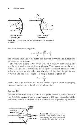
Example 3.3
Calculate the focal length of the Cassegrain mirror system shown in
Fig. 3.9 if the radius of the primary mirror is 200 mm, the radius of the
secondary mirror is 50 mm, and the mirrors are separated by 80 mm.
Figure 3.9 Cassegrain mirror
system. The image formed by
the primary mirror is the virtual
object for the secondary mirror.