
Page 156 - Modular design for machine tools
P. 156
116 Modular Design Guide and Machine Tools Description
X Z
Y d
Z
W
Y
X
XYZOCv COZXbwd
Work branch Tool branch
(a) (b)
Z Z
C
X X
Y Y
D
u
d
DuOX(CZ)v dO(X4A + Y4B H + Z5C )
V
(c) (d)
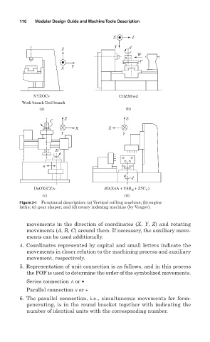
Figure 3-1 Functional description: (a) Vertical milling machine; (b) engine
lathe; (c) gear shaper; and (d) rotary indexing machine (by Vragov).
movements in the direction of coordinates (X, Y, Z) and rotating
movements (A, B, C) around them. If necessary, the auxiliary move-
ments can be used additionally.
4. Coordinates represented by capital and small letters indicate the
movements in closer relation to the machining process and auxiliary
movement, respectively.
5. Representation of unit connection is as follows, and in this process
the FOF is used to determine the order of the symbolized movements.
Series connection < or •
Parallel connection < or +
6. The parallel connection, i.e., simultaneous movements for form-
generating, is in the round bracket together with indicating the
number of identical units with the corresponding number.