
Page 158 - Modular design for machine tools
P. 158
118 Modular Design Guide and Machine Tools Description
v (C) v (C)
A A
u (Z)
a(Z)
a (X) X u (X)
X WP WP
Z
C Z C
Y B
Y B
(a) (b)
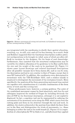
Figure 3-3 Relative movements of cutting tool and work: (a) Cylindrical turning and
(b) face turning (courtesy of Saljé).
are integrated with the coordinates to clarify their spatial allocation,
resulting, e.g., in a(Z), u(x), and v(C) in face turning. As a result, Saljé
and Redeker suggested that the functional description enables poten-
tial configurations to be brought in relief, some of which are often dif-
ficult to envision by the designer. On the basis of such knowledge,
furthermore, they asserted that the structural configuration may be
varied by the relative allocation of the guideway to the floor and by both
the size and the weight of the work to be machined [5]. Figure 3-4
shows some layout drawings and related functional descriptions
after all possible variants have been chosen [6], and as can be seen,
the description method is very similar to that of Vragov, except that it
uses WP instead of O. In addition, the coordinates were determined in
accordance with the VDI-Richtlinie 3255, and a solidus (slash) is
employed to distinguish the movement of the workpiece branch. More
specifically, the analysis of the form-generating movement was carried
out together with consideration of a suitable combination of the form
entity of work and the cutting tool.
These predecessors have, however, a serious problem: The order of
the symbolized movement cannot be fixed absolutely, and thus Ito and
colleagues improved the method of Vragov by including obviously the
idea of FOF in the functional description, although it is not explicitly
displayed. In fact, a machine tool can be represented by ordering the
movements of the structural units along the FOF, which starts from the
cutting point and flows in the structure through the tool and work. In
addition, the slash is allocated at the position from which the force flows
out to the floor and distinguishes the kinds of movements, i.e., those
belonging to either the tool or the work branch [7]. Figure 3-5 is a repro-
duction of a description for TC by Saito et al., and afterward they applied