
Page 163 - Modular design for machine tools
P. 163
Description of Machine Tools 123
(a)
(b)
(c)
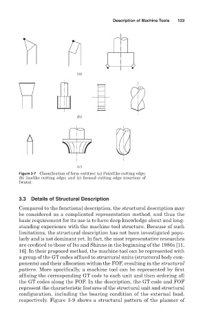
Figure 3-7 Classification of form entities: (a) Pointlike cutting edge;
(b) linelike cutting edge; and (c) formed cutting edge (courtesy of
Iwata).
3.3 Details of Structural Description
Compared to the functional description, the structural description may
be considered as a complicated representation method, and thus the
basic requirement for its use is to have deep knowledge about and long-
standing experience with the machine tool structure. Because of such
limitations, the structural description has not been investigated popu-
larly and is not dominant yet. In fact, the most representative researches
are credited to those of Ito and Shinno in the beginning of the 1980s [11,
16]. In their proposed method, the machine tool can be represented with
a group of the GT codes affixed to structural units (structural body com-
ponents) and their allocation within the FOF, resulting in the structural
pattern. More specifically, a machine tool can be represented by first
affixing the corresponding GT code to each unit and then ordering all
the GT codes along the FOF. In the description, the GT code and FOF
represent the characteristic features of the structural unit and structural
configuration, including the bearing condition of the external load,
respectively. Figure 3-9 shows a structural pattern of the planner of