
Page 167 - Modular design for machine tools
P. 167
Description of Machine Tools 127
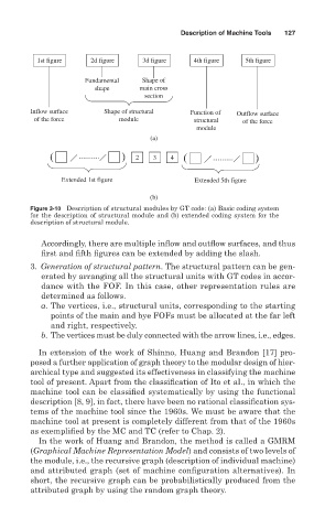
1st figure 2d figure 3d figure 4th figure 5th figure
Fundamental Shape of
shape main cross
section
Inflow surface Shape of structural Function of Outflow surface
of the force module structural of the force
module
(a)
2 3 4
Extended 1st figure Extended 5th figure
(b)
Figure 3-10 Description of structural modules by GT code: (a) Basic coding system
for the description of structural module and (b) extended coding system for the
description of structural module.
Accordingly, there are multiple inflow and outflow surfaces, and thus
first and fifth figures can be extended by adding the slash.
3. Generation of structural pattern. The structural pattern can be gen-
erated by arranging all the structural units with GT codes in accor-
dance with the FOF. In this case, other representation rules are
determined as follows.
a. The vertices, i.e., structural units, corresponding to the starting
points of the main and bye FOFs must be allocated at the far left
and right, respectively.
b. The vertices must be duly connected with the arrow lines, i.e., edges.
In extension of the work of Shinno, Huang and Brandon [17] pro-
posed a further application of graph theory to the modular design of hier-
archical type and suggested its effectiveness in classifying the machine
tool of present. Apart from the classification of Ito et al., in which the
machine tool can be classified systematically by using the functional
description [8, 9], in fact, there have been no rational classification sys-
tems of the machine tool since the 1960s. We must be aware that the
machine tool at present is completely different from that of the 1960s
as exemplified by the MC and TC (refer to Chap. 2).
In the work of Huang and Brandon, the method is called a GMRM
(Graphical Machine Representation Model) and consists of two levels of
the module, i.e., the recursive graph (description of individual machine)
and attributed graph (set of machine configuration alternatives). In
short, the recursive graph can be probabilistically produced from the
attributed graph by using the random graph theory.