
Page 166 - Modular design for machine tools
P. 166
126 Modular Design Guide and Machine Tools Description
leading areas to be carried out by the methodology of modular design,
i.e., the principle of adaptation.
In the following, the details of the description and its procedure will
be stated.
1. Description of FOF. Under the classification of the FOF into the three
types, i.e., main, bye, and virtual FOFs, the description rules have
been determined as shown in Table 3-3, where each FOF is defined
as follows.
Main FOF: Flowing in the structural body from the machining point
of tool branch and flowing out to the factory floor.
Bye FOF: Flowing in the structural body from the machining point
of the work branch and merging, in principle, into the main FOF
within a machine.
Virtual FOF: Diverging from main or bye FOF and stopping at the
terminal structural unit. The virtual FOF is not required of the
description procedure; however, it could be necessary when the basic
layout drawing will be produced from the structural pattern.
2. Coding of the structural units within the FOF. Here the GT code of
five figures is predetermined as shown in Fig. 3-10 and Table 3-4. In
coding, the second, third, and fourth figures represent the shape,
main cross-sectional shape, and dominant function of the structural
unit, respectively. In addition, the first and fifth figures show the
inflow and outflow surfaces in each structural unit of the FOF.
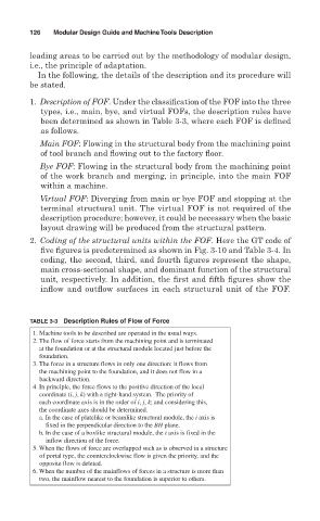
TABLE 3-3 Description Rules of Flow of Force
1. Machine tools to be described are operated in the usual ways.
2. The flow of force starts from the machining point and is terminated
at the foundation or at the structural module located just before the
foundation.
3. The force in a structure flows in only one direction: it flows from
the machining point to the foundation, and it does not flow in a
backward direction.
4. In principle, the force flows to the positive direction of the local
coordinate (i, j, k) with a right-hand system. The priority of
each coordinate axis is in the order of i, j, k; and considering this,
the coordinate axes should be determined.
a. In the case of platelike or beamlike structural module, the i axis is
fixed in the perpendicular direction to the BH plane.
b. In the case of a boxlike structural module, the i axis is fixed in the
inflow direction of the force.
5. When the flows of force are overlapped such as is observed in a structure
of portal type, the counterclockwise flow is given the priority, and the
opposite flow is deleted.
6. When the number of the mainflows of forces in a structure is more than
two, the mainflow nearest to the foundation is superior to others.