
Page 168 - Modular design for machine tools
P. 168
128 Modular Design Guide and Machine Tools Description
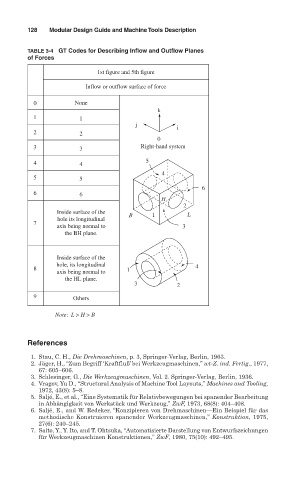
TABLE 3-4 GT Codes for Describing Inflow and Outflow Planes
of Forces
1st figure and 5th figure
Inflow or outflow surface of force
0 None
k
1 1
j
i
2 2
0
3 3 Right-hand system
4 4 5
4
5 5
6
6 6
H
2
Inside surface of the B 1 L
hole its longitudinal
7
axis being normal to 3
the BH plane.
Inside surface of the
hole, its longitudinal
8 1 4
axis being normal to
the HL plane.
3 2
9 Others
Note: L > H > B
References
1. Stau, C. H., Die Drehmaschinen, p. 3, Springer- Verlag, Berlin, 1963.
2. Jäger, H., “Zum Begriff ‘Kraftfluß’ bei Werkzeugmaschinen,” wt-Z. ind. Fertig., 1977,
67: 605–606.
3. Schlesinger, G., Die Werkzeugmaschinen, Vol. 2. Springer- Verlag, Berlin, 1936.
4. Vragov, Yu D., “Structural Analysis of Machine Tool Layouts,” Machines and Tooling,
1972, 43(8): 5–8.
5. Saljé, E., et al., “Eine Systematik für Relativbewegungen bei spanender Bearbeitung
in Abhängigkeit von Werkstück und Werkzeug,” ZwF, 1973, 68(8): 404–408.
6. Saljé, E., and W. Redeker, “Konzipieren von Drehmaschinen—Ein Beispiel für das
methodische Konstruieren spanender Werkzeugmaschinen,” Konstruktion, 1975,
27(6): 240–245.
7. Saito, Y., Y. Ito, and T. Ohtsuka, “Automatisierte Darstellung von Entwurfszeichungen
für Werkzeugmaschinen Konstruktionen,” ZwF, 1980, 75(10): 492–495.