
Page 157 - Modular design for machine tools
P. 157
Description of Machine Tools 117
7. The units that loaded the workpiece and fixed the tool are allocated
to the far left and far right in the description, respectively.
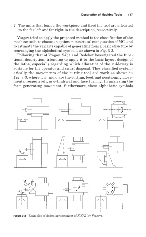
Vragov tried to apply the proposed method to the classification of the
machine tools, to choose an optimum structural configuration of MC, and
to estimate the variants capable of generating from a basic structure by
rearranging the alphabetical symbols, as shown in Fig. 3- 2.
Following that of Vragov, Saljé and Redeker investigated the func-
tional description, intending to apply it to the basic layout design of
the lathe, especially regarding which allocation of the guideway is
suitable for the operator and swarf disposal. They classified system-
atically the movements of the cutting tool and work as shown in
Fig. 3-3, where v, u, and a are the cutting, feed, and positioning move-
ments, respectively, in cylindrical and face turning. In analyzing the
form-generating movement, furthermore, these alphabetic symbols
Figure 3-2 Examples of design arrangement of XOYZ (by Vragov).