
Page 206 - Modular design for machine tools
P. 206
166 Modular Design Guide and Machine Tools Description
.
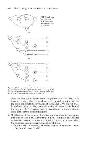
S H : Spindle head
.
.
S H Cv C S T v C : Column
v
.
C S : Cross slide
.
S B : Slide & base
T : Table
v
.
S B
(a)
.
.
S H S B (1)
.
.
C S S B (2)
.
C v S B (3)
.
Cv S B (4)
.
.
C S S B (5)
(b)
.
T v S B (1)
.
.
C S S B (2)
.
C v S B (3)
.
C v S B (4)
.
.
C S S B (5)
(c)
Figure 4-31 Conjunction pattern of module complexes:
(a) General conjunction pattern; (b) conjunction pattern
for unit complexes in tool branch; and (c) conjunction pat-
tern for unit complexes in workpiece branch.
More specifically, the initial structure is positioned within the (X, Y, Z)
coordinate, where the volume element corresponding to the machin-
ing space can facilitate correlation of the main FOF to the sub-FOF.
In addition, the machining space volume is a virtual one and allocated
the origin of (X, Y, Z), corresponding correctly to the leading dimen-
sions of the actual machining space.
3. Modification of the structural configuration by allocating necessary
functions to each module, resulting in the determination of the joint
surface. In this case, an initial structural candidate can accommodate
the following information processing capabilities.
a. Determination of volume elements (structural modules) with trav-
eling or stationary function