
Page 205 - Modular design for machine tools
P. 205
Application of Machine Tool Description to Engineering Design 165
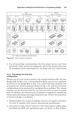
File I File II
(Conventional MC) D. F. 4 D. F. 1 (MC for small parts)
Spindle head complex
D. F. 2
D. F. 3
D. F. 2
D. F. 1 D. F. 2 D. F. 1 D. F. 2 D. F. 3
Column complex
Cross slide complex D. F. 2 D. F. 2
Slide & base complex D. F. 1 D. F. 1
D. F. 0 D. F. 1 D. F. 2 D. F. 1 D. F. 2
Table complex
D. F. : Degree of freedom in movement function
Figure 4-30 File of module complexes.
2. Use of knowledge representation for the design factors and their
standards of the structural component, where the design factor and
its standard can be represented by the flame and rule, respectively
4.2.3 Free design for structural
configuration
Shinno and Ito once tried to produce the concept drawing with the free
design [22]. In this trial, a hierarchical modular system was employed
as shown in the design flow in Fig. 4-34, where the basic modules are,
in general, the volume elements shown in Fig. 4-35, and the structural
configuration can be produced by combining these modules. The volume
element can be characterized by its data structure of gravity-origin
type. In addition, the idea of a pair of modules is employed, considering
furthermore the fixing and supporting functions. In fact, the procedure
of this free design is as follows.
1. Determination of a group of modules that are arranged in the form
of a pair of modules with relative dimensional specifications.
2. Generation of the initial structure with dimensional information
including the FOF and machining space, as shown in Fig. 4-36(a).