
Page 204 - Modular design for machine tools
P. 204
164 Modular Design Guide and Machine Tools Description
F
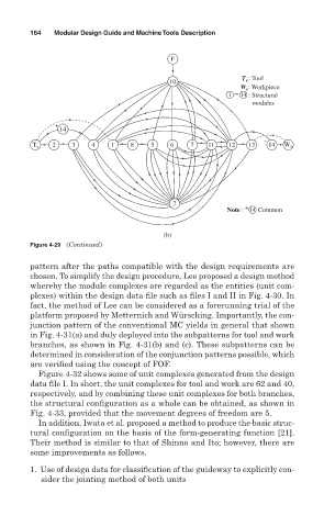
: Tool
10 T v
W : Workpiece
v
1 ~ 14 : Structural
modules
14
T v 2 3 4 1 8 5 6 7 11 12 13 14 W v
7
+
Note : Common
14
(b)
Figure 4-29 (Continued)
pattern after the paths compatible with the design requirements are
chosen. To simplify the design procedure, Lee proposed a design method
whereby the module complexes are regarded as the entities (unit com-
plexes) within the design data file such as files I and II in Fig. 4-30. In
fact, the method of Lee can be considered as a forerunning trial of the
platform proposed by Metternich and Würsching. Importantly, the con-
junction pattern of the conventional MC yields in general that shown
in Fig. 4-31(a) and duly deployed into the subpatterns for tool and work
branches, as shown in Fig. 4-31(b) and (c). These subpatterns can be
determined in consideration of the conjunction patterns possible, which
are verified using the concept of FOF.
Figure 4-32 shows some of unit complexes generated from the design
data file I. In short, the unit complexes for tool and work are 62 and 40,
respectively, and by combining these unit complexes for both branches,
the structural configuration as a whole can be obtained, as shown in
Fig. 4-33, provided that the movement degrees of freedom are 5.
In addition, Iwata et al. proposed a method to produce the basic struc-
tural configuration on the basis of the form-generating function [21].
Their method is similar to that of Shinno and Ito; however, there are
some improvements as follows.
1. Use of design data for classification of the guideway to explicitly con-
sider the jointing method of both units