
Page 200 - Modular design for machine tools
P. 200
160 Modular Design Guide and Machine Tools Description
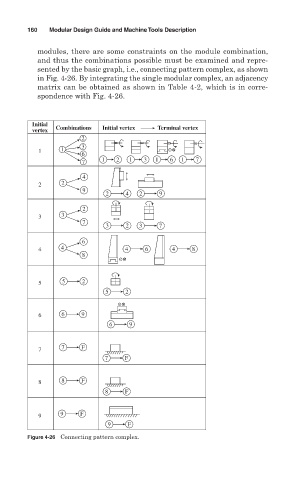
modules, there are some constraints on the module combination,
and thus the combinations possible must be examined and repre-
sented by the basic graph, i.e., connecting pattern complex, as shown
in Fig. 4-26. By integrating the single modular complex, an adjacency
matrix can be obtained as shown in Table 4-2, which is in corre-
spondence with Fig. 4- 26.
Initial Combinations
vertex Initial vertex Terminal vertex
2
3
1 1
6
1 2 1 3 1 6 1 7
7
4
2 2
9
2 4 2 9
2
3 3
7
3 2 3 7
6
4 4 4 6 4 8
8
5 5 2
5 2
6 6 9
6 9
7 7 F
7 F
8 8 F
8 F
9 9 F
9 F
Figure 4-26 Connecting pattern complex.