
Page 201 - Modular design for machine tools
P. 201
Application of Machine Tool Description to Engineering Design 161
TABLE 4-2 Adjacency Matrix of Connecting Pattern Complex
Terminal vertex
1 2 3 4 5 6 7 8 9
1 0 1 1 0 0 1 1 0 0
2 0 0 0 1 0 0 0 0 1
3 0 1 0 0 0 0 1 0 0
Initial vertex 4 5 6 0 0 1 0 0 0 0 0 0 0 0 1 0 0 0 1 0 0 0 0 1
0
0
0
0
0
0
7 0 0 0 0 0 0 0 0 0
8 0 0 0 0 0 0 0 0 0
9 0 0 0 0 0 0 0 0 0
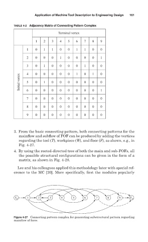
3. From the basic connecting pattern, both connecting patterns for the
mainflow and subflow of FOF can be produced by adding the vertices
regarding the tool (T), workpiece (W), and floor (F), as shown, e.g., in
Fig. 4- 27.
4. By using the rooted-directed tree of both the main and sub-FOFs, all
the possible structural configurations can be given in the form of a
matrix, as shown in Fig. 4-28.
Lee and his colleagues applied this methodology later with special ref-
erence to the MC [20]. More specifically, first the modules popularly
T v 1 2 3 4 5 6 7 8 9 F v
Figure 4-27 Connecting pattern complex for generating substructural pattern regarding
mainflow of force.