
Page 218 - Modular design for machine tools
P. 218
178 Engineering Design for Machine Tool Joints
0.55
0.50
A n A n +1 0.45
2l n 0.40 n = 200 rev/min 100
Damping factor ψ = 0.35 5
50
0.30
0.25
Nonrotating
0.20
0.15
0 4 8 12 16 20 24 1 mm
Vibration amplitude, mm
Overhang of boring spindle: 300 mm
Continuous line: Nonloading
Broken line: Under load of 20 kgf
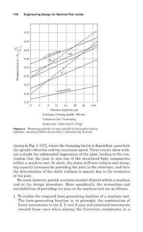
Figure 5-3 Damping capacity of main spindle in horizontal boring
machine, measured from decayed free vibration (by Kunin).
shown in Fig. 5-3 [7], where the damping factor is dependent upon both
the spindle vibration and the rotational speed. These results show with-
out a doubt the substantial importance of the joint, leading to the con-
clusion that the joint is also one of the structural body components
within a machine tool. In short, the static stiffness reduces and damp-
ing capacity increases by providing the joint in the structure, and then
the deterioration of the static stiffness is mainly due to the weakness
of the joint.
We must, however, provide a certain number of joints within a machine
tool in the design procedure. More specifically, the necessities and
inevitabilities of providing the joint to the machine tool are as follows.
1. To realize the required form-generating function of a machine tool.
The form-generating function is, in principle, the combination of
linear movements to the X, Y, and Z axes and rotational movements
around these axes when placing the Cartesian coordinates in a