
Page 220 - Modular design for machine tools
P. 220
180 Engineering Design for Machine Tool Joints
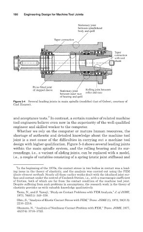
Stationary joint
between spindlehead
body and quill
Taper connection
Taper
connection
with tool
shank
Press-fitted joint
of stepped sleeve Stationary joint Rolling joint between
between outer race roller and race
of bearing and quill
Figure 5-4 Several leading joints in main spindle (modified that of Gebert, courtesy of
Carl Hanser).
2
and acceptance tests. In contrast, a certain number of related machine
tool engineers believe even now in the superiority of the well-qualified
engineer and skilled worker to the computer.
Whether we rely on the computer or mature human resources, the
shortage of authentic and detailed knowledge about the machine tool
joint is a root cause of the difficulties in carrying out a machine tool
design with higher qualification. Figure 5-4 shows several leading joints
within the main spindle system, and the rolling bearing and its sur-
roundings, i.e., a variant of sliding joints, can be replaced with a model,
i.e., a couple of variables consisting of a spring (static joint stiffness) and
2
In the beginning of the 1970s, the contact stress in two bodies in contact was a lead-
ing issue in the theory of elasticity, and the analysis was carried out using the FEM
(finite element method). Nearly all those earlier works dealt with the idealized joint sur-
face and contact under the control of Coulomb friction, i.e., with a macroscopic coefficient
of friction, both of which are far from the contact condition of the machine tool joint.
Despite suffering from such problems in assumptions, the research work in the theory of
elasticity provides us with valuable knowledge qualitatively.
Tsuta, N., and S. Yamaji, “Study on Contact Problems with FEM Analysis,” J. of JSME,
1973, 76(651): 348–358.
Ohte, S., “Analysis of Elastic Contact Stress with FEM,” Trans. JSME (1), 1972, 38(313):
2210–2216.
Okamoto, N., “Analysis of Nonlinear Contact Problem with FEM,” Trans. JSME, 1977,
43(374): 3716–3722.