
Page 223 - Modular design for machine tools
P. 223
Basic Knowledge of Machine Tool Joints 183
Column Column
Guide key
Connecting Taper pin
bolt
Base
Base
(a) (b)
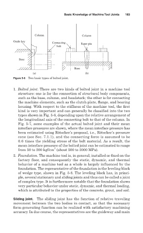
Figure 5-6 Two basic types of bolted joint.
1. Bolted joint. There are two kinds of bolted joint in a machine tool
structure: one is for the connection of structural body components,
such as the base, column, and headstock; the other is for connecting
the machine elements, such as the clutch plate, flange, and bearing
housing. With respect to the stiffness of the machine tool, the first
kind is very important and can generally be classified into the two
types shown in Fig. 5-6, depending upon the relative arrangement of
the longitudinal axis of the connecting bolt to that of the column. In
Fig. 5-7, some examples of the actual bolted joint and their mean
interface pressures are shown, where the mean interface pressure has
been estimated using Rötscher’s proposal, i.e., Rötscher’s pressure
cone (see Sec. 7.1.1), and the connecting force is assumed to be
0.6 times the yielding stress of the bolt material. As a result, the
mean interface pressure of the bolted joint can be estimated to range
2
from 50 to 200 kgf/cm (about 500 to 2000 MPa).
2. Foundation. The machine tool is, in general, installed or fixed on the
factory floor, and consequently the static, dynamic, and thermal
behavior of a machine tool as a whole is largely influenced by the
foundation. The representative of the foundation is the leveling block
of wedge type, shown in Fig. 5-8. The leveling block has, in princi-
ple, several stationary and sliding joints and thus can be called a joint
of complex type. It is furthermore notable that the foundation shows
very particular behavior under static, dynamic, and thermal loading,
which is attributed to the properties of the concrete, grout, and soil.
Sliding joint. The sliding joint has the function of relative traveling
movement between the two bodies in contact, so that the necessary
form-generating function can be realized with satisfactory machining
accuracy. In due course, the representatives are the guideway and main