
Page 227 - Modular design for machine tools
P. 227
Basic Knowledge of Machine Tool Joints 187
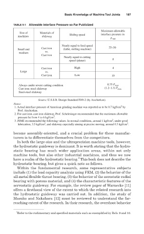
TABLE 5-1 Allowable Interface Pressure so Far Publicized
Maximum allowable
Size of Materials of
Sliding speed interface pressure in
machines slideway
p max
Nearly equal to feed speed
Cast iron 25–30
Small and (lathe, milling machine)
medium vs.
Cast iron
Nearly equal to cutting
speed (planer) 8
Cast iron High 4
Large vs.
Cast iron Low 10
Always under severe cutting condition 0.75 P max
Cast iron–steel slideway (1.2–1.3) P max
Steel-steel slideway
Source: U.S.S.R. Design Standard H49-2 (by Atscherkan).
Notes:
2
1. Actual interface pressure of American grinding machine was reported as to be 0.7 kgf/cm by
Prof. Atscherkan.
2. For cast iron–cast iron slideway, Prof. Schelesinger recommended that the maximum allowable
2
pressure be from 4 to 6 kgf/cm .
2
3. JSME recommended the following values. In normal conditions, around 1 kgf/cm , under good
2
2
lubrication, 3.5 kgf/cm , and slideway especially aiming at precise moving, around 0.3 kgf/cm .
become assembly-oriented, and a crucial problem for these manufac-
turers is to differentiate themselves from the competitors.
In both the large-size and the ultraprecision machine tools, however,
the hydrostatic guideway is dominant. It is worth stating that the hydro-
static bearing has much wider application areas, within not only
machine tools, but also other industrial machines, and thus we now
4
have a realm of the hydrostatic bearing. This book does not describe the
hydrostatic bearing, but gives a quick note as follows.
Within the fundamental research, some representative subjects
include (1) the load capacity analysis using FEM, (2) the behavior of the
all-metal flexible thrust bearing, (3) the behavior of the aerostatic radial
bearing with porous material, and (4) the characteristic features of the
servostatic guideway. For example, the review paper of Warnecke [11]
offers a firsthand view of the extent to which the related research into
the hydrostatic guideway was carried out. In addition, the study of
Masuko and Nakahara [12] must be reviewed to understand the far-
reaching extent of the research. In their research, the overshoot behavior
4
Refer to the rudimentary and specified materials such as exemplified by Refs. 9 and 10.