
Page 224 - Modular design for machine tools
P. 224
184 Engineering Design for Machine Tool Joints
8-f33 40 250 440 250 250 350 40
2-f25 55 55 50 60
160 200 160 490 M26
160 160 605 M30 50 1620 70
95 10-f28 68
185 1035 185 45
1405 (ii) Double column type planer
(i) Double column type planomiller (Billeter A.G., width of table 2500 mm)
(Kollman A.G., width of table 1500 mm)
40 60
40 400 400 400 40 55
300 680
300 M30
1280 40
8-f32
(iii) Double column type planer
(Kinoshita Co. Ltd., width of table 1400 mm)
(a)
Mean interface pressure p, kgf/mm 2
Material of connecting bolt
S45C (JIS) S45C (JIS)
SS41B (JIS) 10 k (DIN)
Normalizing Tempering
Planomiller 0.58 0.87 1.25 2.24
Köllman AG
Planer
Billeter AG 0.30 0.46 0.65 1.17
Planer
0.46 0.71 1.04 1.81
Kinoshita Co.
(b)
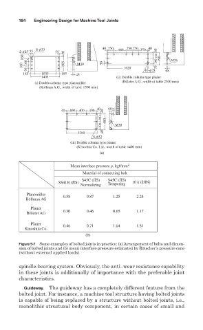
Figure 5-7 Some examples of bolted joints in practice: (a) Arrangement of bolts and dimen-
sion of bolted joints and (b) mean interface pressure estimated by Rötscher’s pressure cone
(without external applied loads).
spindle-bearing system. Obviously, the anti–wear resistance capability
in these joints is additionally of importance with the preferable joint
characteristics.
Guideway. The guideway has a completely different feature from the
bolted joint. For instance, a machine tool structure having bolted joints
is capable of being replaced by a structure without bolted joints, i.e.,
monolithic structural body component, in certain cases of small and