
Page 222 - Modular design for machine tools
P. 222
182 Engineering Design for Machine Tool Joints
joint, in addition to its apparent features and structural configuration,
the following technological aspects should be taken into consideration:
in what way and how much the joint to be considered affects the over-
all behavior of the machine tool. In classifying the joint, moreover, the
joint in a machine-tool-work system, e.g., the joint between the cutting
tool and the work should be incorporated.
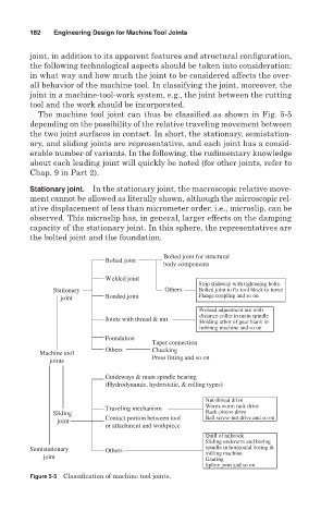
The machine tool joint can thus be classified as shown in Fig. 5-5
depending on the possibility of the relative traveling movement between
the two joint surfaces in contact. In short, the stationary, semistation-
ary, and sliding joints are representative, and each joint has a consid-
erable number of variants. In the following, the rudimentary knowledge
about each leading joint will quickly be noted (for other joints, refer to
Chap. 9 in Part 2).
Stationary joint. In the stationary joint, the macroscopic relative move-
ment cannot be allowed as literally shown, although the microscopic rel-
ative displacement of less than micrometer order, i.e., microslip, can be
observed. This microslip has, in general, larger effects on the damping
capacity of the stationary joint. In this sphere, the representatives are
the bolted joint and the foundation.
Bolted joint for structural
Bolted joint
body components
Welded joint
Strip slideway with tightening bolts
Stationary Others Bolted joint to fix tool block to turret
joint Bonded joint Flange coupling and so on
Preload adjustment nut with
distance collar in main spindle
Joints with thread & nut
Holding arbor of gear blank in
hobbing machine and so on
Foundation
Taper connection
Others Chucking
Machine tool
joints Press fitting and so on
Guideways & main spindle bearing
(Hydrodynamic, hydrostatic, & rolling types)
Nut-thread drive
Worm-worm rack drive
Traveling mechanism
Sliding Rack-pinion drive
joint Contact portion between tool Ball screw-nut drive and so on
or attachment and workpiece
Quill of tailstock
Sliding underarm and boring
Semistationary Others spindle in horizontal boring &
joint milling machine
Gearing
Spline joint and so on
Figure 5-5 Classification of machine tool joints.